• New!: AI applied to 3D printing
• Sensor Tip: Avoiding sensor-related Machine Downtime
• Application: System for "laying away" sails
• and more. |
To view newsletter in your browser click here.
|
|
AI applied to 3D printing |
| | | |
| | | |
| | | |
Artificial Intelligence Applied To 3D Printing
Researchers at MIT set out to solve the problem of having to repeat a 3D printing process many times to iteratively adjust for imperfections and inconsistencies when printing on a new or unfamiliar material.
They successfully applied a machine learning technique to improved on printing accuracy over other 3D printing controllers when complex control is needed.The methodology they used was to use two monitoring cameras and adjust printing parameters in real time. The parameters included feed rate and direction of printing.
Instead of making an enormous amount of 3D prints to gather the data necessary to "train their controller," the MIT team built a simulator that would attempt to minimize printing errors including when simulated printing "noise" was applied.
The researchers plan to build on this success to apply their AI model to multi-layer and multiple materials as well as adjusting for changing viscosity of a material. You can read the formal paper with all the technical details and math on this as it is linked to in source number two. |
| | | |
 |
Specifying and Setting Up of Position Sensors to Avoid / Minimize Machine Downtime
Most all motion-controlled machines today are fitted or retrofitted with position sensors. These sensors are designed to track mechanical movements and output electrical values that are linearly proportional to the position of the sensor's rod, shaft or floating marker. This output is fed either to a signal conditioner or directly to a controller.
Machines used in high-accuracy operations and often in challenging environments, are also required to be retrofitted with sensing devices that meet those environmental requirements as well as keeping their performance characteristics throughout. Engineers and maintenance mechanics understand equipment components need to be specified to allow for expected environment temperature extremes, vibration, moisture and/or wash-down exposure and mechanical connection degradation over time — especially from exposure to moisture and vibration.
The first step in avoiding future machine downtime from a sensor issue is during the design and selection phases of the system it is to be integrated in. A sensor is selected by the electrical engineers for power, input and output requirements to successfully provide accurate feedback information needed to be treated by the systemʼs controller and electronics.
The first step is made easier in the sense that the position sensor type selection often comes after the mechanical system to be integrated in has been designed and its electrical and electronic control methodology determined; in other words, very seldom machines are designed around one sensor. The stroke length or (for rotary applications) angular range, power requirements and, likely already specified, machineʼs controller often dictate a sensorʼs power and output requirements.
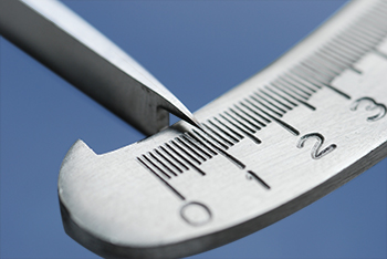
Equally as important is determining the accuracy, resolution, linearity, repeatability, shock, vibration and sealing requirements of the position sensor for your application. One rule of thumb is that you need a sensor to have a resolution of about 10 times the smallest increment you need to measure. If you need to know the position within one mm, then you need a sensor with 0.1 mm resolution or better. Same for rotary sensors. If you need to measure to one degree, you need a device with 0.1 degree of resolution or better. For more information on determining the accuracy needed, see our past newsletter technical article here.
|
Choosing a sensor with higher shock and vibration specifications amongst various brands of position sensors is a safe way to go for minimizing downtime from repeated vibration and shock that occurs on heavy machinery with moving parts.
Our past article on the subject of determining requirements for shock and vibration can be found here.
Determining the amount of sealing or protection needed. Sealing is specified by a position sensor's IP rating can prevent downtime caused by exposure in wet environments such as spilling liquids or if a wash-down requirement on needed for your machine. Sensors require protection from not only the environment, but also from other electrical devices and conductors. Almost all sensors are environmentally rated for ingress protection (IP), temperature rating (in °C or °F), as well as electrical rated (IEC). So, either selecting a sensor that has an IP rating that meets your applications expected requirements for exposure to water and/or dust or using the proper NEMA (National Electrical Manufacturer Association) rated enclosure will allow for a safe operating environment of the sensor.
The second step is when the sensor is mechanically installed, aligned, coupled, connected and protected using sound engineering principles of Failure Modes and Effects Analysis (FMEA). Failure modes refers to the ways in which a product could fail. Effects Analysis is determining the cause or causes of the failure(s).
The focus for the second step is the sensor's mechanical constraints of rigidity and displacement stability during its sensing operation.
The sensor's installation requires choosing a stable physical platform to accommodate its physical features such as mounting holes patterns to properly secure the sensor, body clearance and interference to prevent foreign elements from moving the sensor during operation.
For non-contacting magnetic sensors, The alignment of the sensor parallel to the magnet and the magnet firmly attached to the moving part of your product's moving part is of utmost importance in the sense that it allows an accurate positioning of the driving and driven device. For shafted and potentiometric types, the sensor needs to be mounted so that the shaft is as close to perpendicular to the surface of the part it is mounted to as possible.
This alignment ensures the proper and stable coupling of the driven and driving device as well as the elimination of potential negative effects such as side-loading which could strain the mechanical assembly and produce feedback values with hysteresis, backlash and non-linearity errors. For touchless systems, magnets markersʼ improper coupling can lead to weak magnetic flux if the wrong distance is maintained or the wrong material surrounding the magnet is selected; (i.e. carbon steel).
The sensor electrical connection is considered a mechanical action as it allows the mechanical coupling of physical metallic wires to conduct electrical current from the sensor to the reader/controller. The soldering or clamping of conductors is critical in getting an uninterruptible current flow and avoiding shorting or loss of signal caused by loose or broken wires due to excess vibration, crushed conductors or thermal relaxation. The sensor conductorʼs color-coded functions as supply power, common and signal outputs wires need to always match as they are the base for obtaining the proper feedback signal.
Should a position sensor seem to fail, it often pays to power-down, remove the sensor and check the contacts for corrosion. If present, remove the corrosion from the contacts on the sensor. Reinstall the position sensor after cleaning the contacts, apply power and you may be back in operation right away.
Ensuring these different requirements and good practices of sensors are met, not only help machines perform at peak, but also help reduce costly machine downtime.
|
| | | |
System for "Laying Away" Sails
| | | |
| | | |
On large and very expensive ocean going yachts many of the operations are fully automated. Our customer is a British company that specializes in supplying hydraulic systems for this market. One of their most recent applications was a system for "laying away" the sails after a days sailing.
• Electrically it was as easy to use as a potentiometer
• Once fitted inside a hydraulic cylinder it was perfectly protected from the harsh marine environment
|
|
• It is an absolute transducer
• Repeatability
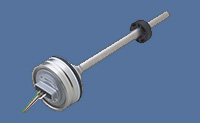
The TM1 was fitted inside a hydraulic cylinder to measure its extension. Repeatability of the TM1 is ≤ 0.1 mm. The cylinder is used to raise and lower the boom to which the main sail is attached. The space available to pack the sail away is very limited so if the whole process is to be automated then precise positioning of the boom is required.
Learn more.
|
| | | |
| | | |
 |
| |
| Please email suggestions for technical subjects you would like to suggest for this newsletter to this link: Newsletter Editor |
| | | | |
| |
|