Novotechnik FAQs & Application Notes

CALL 1-800-667-7492

T: 1-800-667-7492
FAQs
- 1) How do I calculate resolution for Novotechnik's Vert-X rotary position sensor products?
A: Resolution = 12 bit = 212 = 4096 points or increments for full rotation
I . The 700 series MH-C technology provides 12-bit resolution over the programmed function angle.
II. Examples:
i. If the function angle of the sensor is 360 degrees then you will have a readable change every 0.09°. (360/4096 = -0.09)
ii. If the function angle of the sensor is 90 degrees then you will have a readable change every 0.022°. (90/4096 = 0.022)
- 2) What are the differences between the Vert-X "700" series and the "200" series?
A: The 700-series do have the advantage that the resolution is always on the programmed electrical angle, except for very small angles (below 30°).
That means if you have an electric angle of 120° for example and a ratio metric output (12bit = 4096 steps) you have a resolution of 0.03°. With a Vert-X of the 200-series the resolution is always on 360°.
That means you do have a resolution of 0.09° independent of the electrical angle. For very small angles (below 30°) the noise will be a parameter which is no more insignificant, means the resolution is so low that the noise does have an influence.
We expect a resolution of about 0.01° and a linearity of about ± 0.5% at an angle of 10° with the 700-series. With the 200-series the resolution will be 0.09° and the linearity about ±0.3% Summary: For electrical angle smaller than 360° the 700-series does have the big advantage that the resolution (in degrees) will be better than the 200-series. The linearity is stable in both cases for angles between 30° and 360°.
- 3) What is the recommended input impedance for Novotechnik position sensors, position transducers and potentiometers?
A: The recommended current draw on a potentiometer is 1µA (1 micro Amp = 0.000001 Amps).
I . The voltage supply to the potentiometer can vary (up to 42 Volts typically).
II . Input impedance = R, where R = voltage/current
i. R = 10V / 0.000001Amps = 10,000,000 Ω = 10 Mega Ω
ii. A 10 Mega Ω input impedance is what is recommend to have on your data acquisition card or PLC input to insure that too much current is not drawn across the wiper of the potentiometer.
iii. If the input impedance in this case were only 1 Mega Ω, then you would be introducing a linearity error of less than 0.1%. Using and input impedance of 100kΩ or less not only will introduce linearity errors, but can degrade the life of the pot due to excessive heat on the element itself.
- 4) What is the definition of accuracy for position sensors, position transducers and potentiometers?
A: It is a function of linearity and function angle.
I. If a potentiometer has a linearity specification of +/- 0.1% and an electrical function angle of 345° accuracy would be calculated as follows: a. 0.1/100 x 345 = +/- 0.3° accuracy.
- 5) How does temperature effect the output signal?
A: Perform a voltage drift calculation:
I. A recent scenario presented itself where an application required an MUP signal conditioner and a P6501a502 potentiometer. They indicated that they would be setting up the sensor at room temperature (-68°F). They also indicated that the temperature where their application was located could range from -50°F to -90°F. They wanted to know what the effects of temperature change would have on the output signal they received.
II. Calculation
i. Add up ppm/K (parts per million divided by degrees Kelvin) specification for all products involved.
1. In this case the Temp Coefficient for the MUP is 20ppm/K and the Temp Coefficient for the P6500 is 5 ppm/K. Total = 25ppm/K
ii. Determine maximum temperature differential from temperature that the sensor is set up at. In this case room temperature (-68°F). Convert these temps to Celcuis for calculation purposes
1. 68°F = 20°C (calculation = 68°F - 32 x 0.5556 = 20°C)
2. 50°F = 10°C (calculation = 50°F - 32 x 0.5556 = 10°C
3. 90°F = 32°C (calculation = 90°F - 32 x 0.5556 = 32°C)
a. The largest temp drift (differential) is between 20°C and 32°C = 12°C = 12°K
iii. Final Calculation of Voltage Drift due to temperature change
1. Drift Factor = 25ppm/K x 12°K = 300/1,000,000 = 0.0003 or 0.03%
2. Supply Voltage x Drift Factor = Voltage Drift
a. Example:10VDC x 0.0003 = 0.003V = 3mV Voltage Drift due to temperature
- 6) How do I calibrate MAP300 Series Process Monitors?
A: Use the following calibration procedure:
I. Attach leads from potentiometer sensor to MAP.
i. Pin 1 from the sensor to Terminal 36 on the MAP.
ii. Pin 2 from the sensor to Terminal 33 on the MAP.
iii. Pin 3 from the sensor to Terminal 31 on the MAP.
II. Apply power to MAP (Terminals 1 and 2).
III. Set DECIMAL POINT on the MAP display
i. Hold down the SEL button on the MAP until FUNC is displayed then release the SEL button.
ii. Press the SEL button until C is displayed in the lower left hand corner display window.
iii. Use the ▲ and ▼ arrows to adjust the decimal place position desired.
iv. Press the SEL button until the lower left hand corner display window is clear. You are now out of the FUNC mode.
IV. Set CALIBRATION POINTS on the MAP display.
i. Press and hold the C, SEL and ▼ arrow at the same time until ▲ is displayed on the MAP, then release and IMMEDIATELY press the SEL button to put the MAP into SETUP mode. SETUP will be displayed on the MAP screen.
i. Hold down the SEL button on the MAP until FUNC is displayed then release the SEL button.
ii. Press the SEL button until the lower left hand display window displays the number 5.
iii. Move the shaft of the sensor to the first position to be calibrated.
iv. Program the first position on the MAP by pressing and holding the SP button and then pressing the ▲ arrow. The MAP will count down 3..2..1 to show that the first position is set.
v. Use the ▲ and ▼ arrows to set the first position value to be displayed.
vi. Press the SEL button until the lower left hand display window displays the number 6.
vii. Move the shaft of the sensor to the second position to be calibrated.
viii. Program the first position on the MAP by pressing and holding the SP button and then pressing the ▲ arrow. The MAP will count down 3..2..1 to show that the second position is set.
ix. Use the ▲ and ▼ arrows to set the second position value to be displayed. Press the SEL button until the lower left hand corner display window is clear. You are now out of the SETUP mode.
- 7) What is the calibration procedure for a linear transducer (without a signal conditioner)?
A: Example = LWG100
I: STEP 1: Determine physical ends of the defined electrical stroke of the sensor.
i. Apply your voltage supply to the sensor. (i.e. 10 Volts)
ii. Attach a Volt Meter to pins 2 & 3 of the sensor.
iii. Attach Voltage supply to pins 1 & 3 of the sensor.
iv. Move the rod on the LWG100 until the Voltage meter reads 1/2 of supply voltage (i.e. 5 Volts).
v. Mark position of this electrical center.
vi. Retract the rod precisely with a 50mm gauge block, 50mm and this is your zero position. Record the voltage reading. (i.e 0.08V).
vii. Extend the rod precisely with a 50mm gauge block, 50mm beyond the center position marked in step #5. and record the votage reading. (i.e. 9.97V).
viii. The Calibration value calculation is 9.97V-0.08V = 9.89V/100mm or 0.0989V/mm.
- 8) What is Galvanic Isolation and what isolation benefit does the MUP150 signal conditioner provide?
A: The MUP150 series is provided with galvanic isolation.
I. The MUP power supply will have a ground connection for the 24V excitation that is provided to this signal conditioner.
II. The output device that the MUP supplies an output signal too, will also be grounded.
III. There is no guarantee that these "grounds" will be on the same level and therefore could produce a ground loop (a buzz or hum or noise on the signal).
IV. The galvanic isolation in the MUP150 prevents these ground loops.
- 9) What is the setup procedure for a linear transducer (with a signal conditioner: MUP, MUK or MUW)?
A: The MUP150 series is provided with galvanic isolation.
I. STEP 1: Determine physical ends of the defined electrical stroke of the sensor.
i. DO NOT USE THE MUP SIGNAL CONDITIONER IN THIS STEP.
ii. Apply your voltage supply to the sensor. (i.e. 10 Volts).
iii. Attach a Volt Meter to pins 2 & 3 of the sensor.
iv. Attach Voltage supply to pins 1 & 3 of the sensor.
v. Move the rod on the LWG100 until the Voltage meter reads 1/2 of supply voltage (i.e. 5 Volts).
vi. Mark position of this electrical center.
vii. Retract the rod precisely with a 50mm gauge block, 50mm and this is your zero position.
II. STEP 2: Calibration with MUP100-1
i. Hook up power supply and LWG to the MUP and put a voltmeter (set on V) on the output of the MUP.
ii. Move the LWG rod to the zero position from #7 above.
iii. Adjust the "zero point trimmer pot" on the MUP so that the voltmeter reads 0 V.
iv. From your physical zero position from #6 above, introduce a 100mm gauge block to move the shaft in exactly 100mm from the zero starting point.
v. Adjust the "range trimmer pot" on the MUP so that the voltmeter reads 10V.
vi. Repeat steps 2-5, until values settle into 0V and 10V without adjustment. (When the range trimmer pot is adjusted, it affects the zero point calibration, which is why these steps need to be repeated).
- 10) What is the setup procedure for a rotary pot (with a signal conditioner.: MUP, MUK or MUW)?
A: Example = P4500 with an MUP signal conditioner
I. STEP 1: Determine the ends of the defined electrical angle of the sensor.
i. DO NOT USE THE MUP SIGNAL CONDITIONER IN THIS STEP.
ii. Apply your voltage supply to the sensor. (i.e. 10 Volts).
iii. Attach a Volt Meter to pins 2 & 3 of the sensor.
iv. Attach Voltage supply to pins 1 & 3 of the sensor.
v. Move the shaft on the P4500 until the Voltage meter reads 1/2 of supply voltage (i.e. 5 Volts).
vi. Mark position of this electrical center.
vii. Rotate the shaft precisely 175 degrees CCW and this is your zero position.
II. STEP 2: Calibration with MUP100-1
i. Hook up power supply and P4500 to the MUP and put a voltmeter (set on V) on the output of the MUP.
ii. Move the shaft to the zero position from #7 above.
iii. Adjust the "zero point trimmer pot" on the MUP so that the voltmeter reads 0 V.
iv. From your physical zero position from #7 above, rotate precisely 350 degrees in the CW direction to calibrate your end point.
v. Adjust the "range trimmer pot" on the MUP so that the voltmeter reads 10V.
vi. Repeat steps 2-5, until values settle into 0V and 10V without adjustment. (When the range trimmer pot is adjusted, it affects the zero point calibration, which is why these steps need to be repeated).
- 11) What is the effect of low temperature on a position sensor, position transducer or potentiometer?
A: Example = LWG
I. LWG is specified for temperatures down to -30°C, Novotechnik cannot test the sensor for lower temperatures.
II. The ink should not be critical also for -40°C but this is only a speculation and not tested at Novotechnik.
III. Plastic parts and internal wires will get hard and rigid and brittle, this can be critical.
IV. Guidance will get stronger, operation force will increase, it may be that the sensor is becomes blocked.
V. Sealing and IP rating can definitely not be guaranteed at low temperatures below the specified working range.
- 12) How do I connect a position sensor?
- 13) How are Novotechnik's TP1 and TH1 non-contacting position sensors programmed?
A: See programming procedure below.
Programming the TP1/TH1 Sensors
The start and end positions of the TP1/TH1 transducers with analog interfaces can be adjusted for your application. The output range (0..10V 10..0V / 0.20mA / etc.) can be completely redefined. Up to two position markers can be recalibrated at the same time via two connector pins and a simple programming procedure.


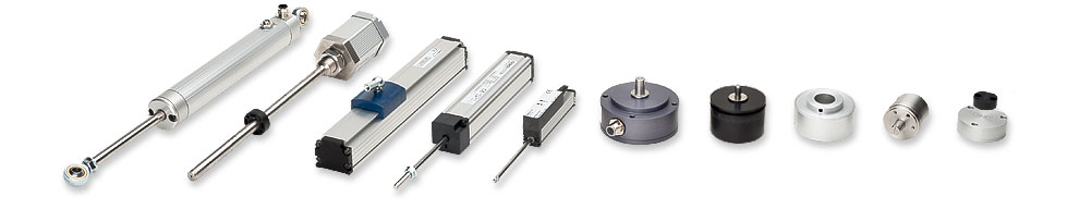
| Rod Type | Touchless | Side Actuated | Rod Type With Return Spring | in-Cylinder | Open Systems |
| Shaft Type | Touchless Rotary | Hollow Shaft | Multi-Turn | Automotive | Open Systems |
| ABOUT | TERMS AND CONDITIONS | PRIVACY |
© 2000-2026 Novotechnik U.S. Inc., All Rights Reserved