|

See the development video.
Source:
Manta5 • https://manta5.com
|
|
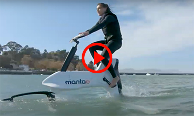
Eight years in development, Manta5 had to overcome several engineering challenges to produce its hydrofoil bicycle, the XE-1. It combines an aircraft aluminum frame with strengthened carbon fiber foils, pedal-driven drivetrain, buoyancy modules and a battery-powered motor-driven propeller. It also floats. The motor produces 460 W of power and the rider selects how much of that power to tap into from seven electric assist control settings. Riders would be able to provide over 50% of the power required to maintain foiling, with 6 mph being the minimum foiling speed.
The front tiller section self-levels as you ride. This design removes the need to self-pitch the foils creating a more stable rider experience as you move through chop and swell. The GARMIN® eBike remote features as the heads-up display to turn the battery on/off as well as adjust the electric assist levels. Riders are able to track and experience additional features such as distance travelled, speed, ride time, heart rate, battery level and electric assist level. The top speed is 13 mph and the battery will supply up to an hour of ride time on the highest level of electric assist.
The XE-1 was designed to be modular for quick and easy assembly/disassembly so that it can be transported in a car or on a roof rack. It weighs about 64 lbs and has assembled dimensions of: 7.2(l) x 6.6(w) x 4.69(h) ft. It needs at least 3 feet of draft below the foils when riding. Manta5 says you can ride it on lakes and ponds, rivers and in the ocean—even biking through small waves. Perhaps Brian Wilson would write a new song—Water-Biking Safari?
|
|
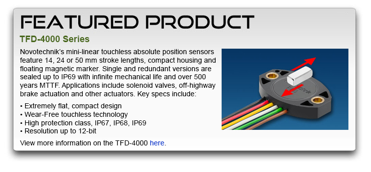
| When a Programmable Angle Sensor Provides Real Advantages and Why It's Easy to Accomplish—Even for Analog Outputs |
 |
Applications that can benefit from programmable angle sensors include:
- Preventing incorrect or undefined states at either end of an angle sensor, especially for actuator or valve applications and any robotics or mobile application
- Control loop applications
- Applications that benefit from multi-point sensor calibration
- High accuracy applications
Additionally, this issue's Sensor Tip section seeks to answer the following questions regarding end-user programming of non-contacting rotary position sensors with analog outputs for general machine automation purposes:
- When does programming after assembly of your product or in the field make sense?
- What type of programmability do I need for my application?
- Is it quick & easy?
- Do I need additional hardware or software for programming start/stop angles?
- How do I protect the programmed sensor from tampering?
Non-contact analog position sensors for use as position feedback devices are very well established across many industries for good reasons: their strong electrical signal, full compatibility with many control systems, simplicity of electrical integration and long term reliability.
Position sensors usually in predefined angles like 30°, 60°, 90°, 180° and 360°. These manufacturer predefined angles are a great option if the application requires an angle just a bit smaller than the ones offered. |
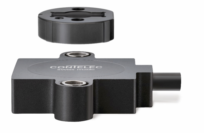
Non-Contact sensor with magnetic marker |
When does programming make sense?
Programming position sensors for start-, mid- and/or end- point makes it easier to precisely calibrate a sensor that is already installed in machinery. This is especially the case for sensors that are installed in locations that are very hard to reach for mechanical adjustment.
One example of a mid-point calibration is a marine manufacturer of hydraulic stabilizer fins for large motor yachts. In order to keep the ship level, gyro sensors detect any undesired movement and actuated fins mounted on the underwater sides of the hull compensate for the movement. The ship's rolling motion can be stopped and the passengers are happy.
The fins need to be calibrated initially for a center position, so the ship stays level and keeps a straight course. In calm waters the ships rudder and fins are positioned for a perfect straight course manually. Then the technician would have to set the screws on the position sensors of at least two fins located in the belly of the ship precisely to show mid position. A very time consuming and finicky procedure that can be shortened to a mere minute when programming the mid points of the fin position sensors from the bridge of the ship. The total measurement angle and sense of rotation were pre-defined and already custom calibrated at the factory.
Let us use a butterfly valve application as an example how to adjust for start and end points. These applications are very common in many industries and usually require an electronic feedback signal provided by an angle sensor. The valve can be operated by various actuators, if the angle is known to the control system, whether it is for applications using DC motors or hydraulic cylinders. Here is a simplified view: |
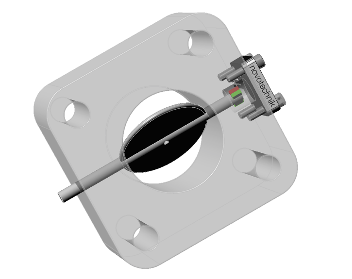
Butterfly valve |
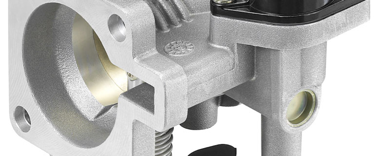
A a real world application is an automobile throttle that incorporates a rotary position sensor. |
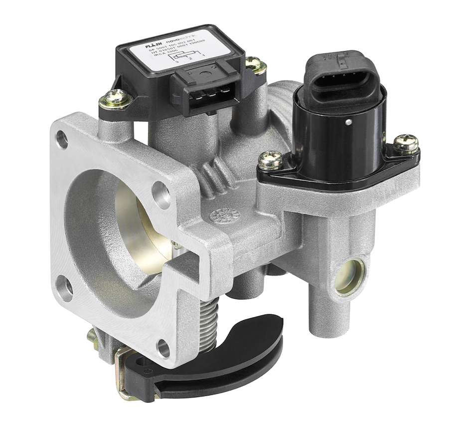
Car engine throttle assembly with butterfly valve, position sensor and small electric motor.
Courtesy of Bosch and Novotechnik. |
The measurement angle required is about 90° from fully closed to wide open. A standard 100° angle position sensor is the optimum in many cases, as there is additional measurement range on both ends available of 5°, which is plenty of reserve to have for compensation of mechanical tolerances inherent to all mechanical components involved. This sensor, typically providing a 0.1V to 10V output, would provide 5.95% of the full-scale output voltage at the closed position and 95% of the output voltage at the wide open position—100% Full Scale equals 10 V in this example. |
Output [%] = Gradient [%/deg] * angle [deg] + ZeroOffsetSensor [%] |
In order for the actuator/motor to drive the valve to the desired position, the controls need to "know" exactly at what voltage the valve will be fully closed and fully open to prevent a mechanical overrun with consequential damages or a valve left open when it needed to be fully closed.
In many industrial and mobile electronics applications the adjustment of the start and end points of the sensor is matched to the mechanical start and end points of the application with a simple rotary adjustment of the sensor and tightening of the mounting screws. During this quick process, the sensor needs to be powered up and a digital voltmeter shows the output voltage, which is then used to correct the rotary position of the sensor to provide the exact output voltage defined for this position.
Depending on what angular position is most important in the application an index point is defined to match a certain position to a certain voltage output, e.g. valve fully closed. With a 100° sensor used in this example, this calibration process would provide a very precise position information of 0.595V at the closed position and roughly 9.5V a the fully open position, assuming again a 90° mechanical angle difference.
If additionally, the "fully open" position feedback needs to be "spot on" and a measurement value provided within the specified absolute linearity of the position sensor is not good enough, a two-point calibration using the programming capabilities of advanced position sensors solves the problem.
A teach-in (programming a selected sensor at a specified angular position) of two mechanical positions at hard mechanical stops provides the most accurate position measurement. Therefore, these teach-in capabilities should be available either in the control system software or in the position sensor itself.
Easy programming steps for different programming needs.
The Contelec Vert-X MH-C2 sensors are available with two additional connections/wires, beyond standard power, ground and signal. This enables simple programming without any additional hardware: |
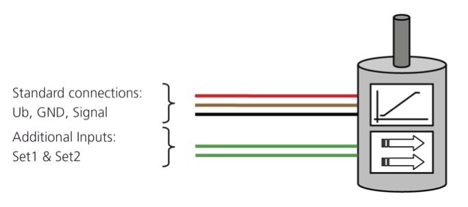
Drawing A - sensor drawn with standard connection wires and programming wires. |
The additional wires, Set1 and Set2, allow for the following adjustments on already installed sensors without the need of any software or hardware:
- Type E: Clockwise (cw) or counter-clockwise (ccw) positive output gradient programming
- Type F: Zero point & cw/ccw positive output gradient programming
- Type G: mid point& cw/ccw positive output gradient programming
- Type H: Start and end point and cw/ccw positive output gradient programming
The parameters created during the programming process are saved in non-volatile memory. Type E, F and G come with a predefined measurement angle, that can be ordered in 10° steps from the factory. Type H allows for gradient and angle programming by using two programming points, the start and the end point.
The programming is carried out by making electrical contact of the additional inputs called Set1 and Set2 to GND of the sensor in defined sequences. The sequences used depend on the Type used: E, F, G or H.
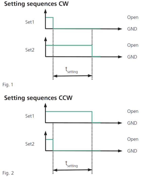
Type E:
To set the positive output gradient to cw, connect Set1 to GND and, within 3 seconds, connect Set2 to GND. See Fig. 1.
To set the positive output gradient to ccw, connect Set2 to GND and, within 3 seconds, connect set1 to GND. See Fig. 2. |
 |
Type F and Type G:
These two sensor types have a similar programming sequence, as both define one point (zero- or mid-point) and the gradient programming.
Turn the sensor into the desired mid-point or zero-point and connect Set1 to GND and within t=3sec Set2 to GND. This sequence programs both the point and the cw direction. If the ccw positive gradient is required, first turn the sensor into the desired position and connect Set2 to GND and then within T=3sec to GND.
Type H:
This preferred type of programmable sensor allows for angular range, cw/ccw definition and two absolute position definitions. The sequences for cw and ccw differ only with the programming wire used for the first point, either Set1 to GND for cw and Set2 for ccw.
Turn the sensor in the desired start position and connect input Set 1 to GND. Within t = 3 sec turn the sensor to the desired end position and connect input Set2 to GND. With that, both the angular range and the sense of rotation to cw are set.
Turn the sensor in the desired start position and connect input Set2 to GND. Within t = 3 sec turn the sensor to the desired end position and connect input Set1 to GND. With that, both the angular range and the sense of rotation to ccw are set.
This type of programming sequences is also very useful in cases, where the sensor is in a remote location and the maintenance crew may not have a lot of electrical equipment on them, e.g. on a oil or gas pipeline valve. Using the knowledge of these simple steps they can install or replace sensors in the field and by setting the output to the machine factory settings retain the same electrical accuracy as specified initially.
Applications, that require different angles for different types of parts, e.g. steering angles or valve opening angles, benefit from this programming option as well, reducing inventory by using one product number and programming it differently.
The programming wires can be cut after the procedure to prevent unwanted re-programming.
The additional cost for these programming functions is only a few Dollars compared to the non-programmable MH-C1 Vert-X sensors models from Contelec.
Key Takeaways
- Position sensor output in control loop applications needs to be calibrated to one or two mechanical positions.
- Mechanical calibration of one index point is straight forward, but secondary points cannot be calibrated with standard sensors and rely on the absolute accuracy of the sensor used.
- Position sensors can be easily calibrated to two points, center and range and positive/negative slope using simple programming steps with no additional knowledge or tools.
- Using programmable position sensors provides exact position definitions and thereby improves the positioning performance of the actuator application.
|
|
|
|

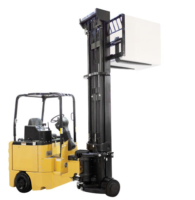
 Forklift Platform Rotation