• Maglev Train Technology
• Sensor Tip: Absolute and Incremental Position Measurement Devices
• Application: High Speed Train Transversal Centering
• and more. |
|---|
To view newsletter in your browser click here.
|
|---|
|
| | | |
| | | |
| | | |
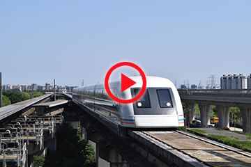
Maglev Train Technology and U.S. Use
|
|
The magnetic levitating (maglev) train was first introduced in Great Britain as a low speed transport for a short distance in 1984. The concept was first imagined and idea introduced in the U.S. in the 1940s by the “rocket scientist” Robert Goddard in 1904 and a professor and engineer Emile Bachelet in the early 1910s. Then in the late 1960s, technology was imagined by James Powell and then patented at Brookhaven National Laboratory by James Powell and Gordon Danby for a magnetically levitated train design. 1,2,3
|
|---|
| | | |
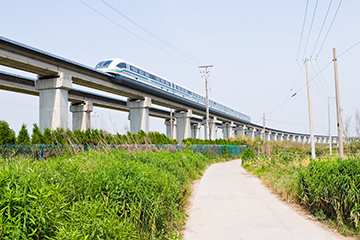
Today maglev trains using either conventional electromagnets attached to the undercarriage of the train and built into the rails or super-cooled superconducting magnets. These trains operate in Europe, China and Japan. The fastest train is in Japan, currently in the testing phase, on the Yamanashi Maglev Line and it travels at up to 375 mph. By way of comparison, Amtrack high-speed trains run at about 150 mph max.3,4 By suspending the train a small space above the track and making the train aerodynamic, friction is reduced to enable much higher speeds.
In traditional trains the running gear including steel wheels, suspension and brakes are referred to as bogeys. These and the platforms connecting two train cars or sections, all require motion control. In maglev trains electromagnets replace the need to have driven- and braked wheels and suspension parts. Some maglev trains reportedly still need wheels and axles to initiate motion and below a certain speed. The reason is that these trains have to be moving at a minimum speed as it floats above the rails, to have alternating poled magnet sets propel the train, levitate it and keep it in line.
The coils are powered with AC current and this changing polarity causes the magnetic field in front of the train to pull the train forward, while the field behind the train repels or pushes it forward.3 Active controls with feedback loops are used in some systems to maintain the distance between the train and the rails within required minimum and maximum distances of typically 8 to 12 mm. In other systems, a self-stabilizing magnetics approach is used that requires retractable wheels to achieve a minimum speed for the electromagnets to introduce the forces required for stable levitation of 10 cm and propulsion.5
An interesting video, made by professor Eric Laithewaite in 1975, of electromagnetic basics can be viewed here. An alternating electromagnetic propulsion demonstration starts at about the 10 minute mark.6
A maglev train line in the U.S. has been proposed to go between Washing D.C. and New York City, with Japan Railway offering to pay for part of it. |
|---|
| | | |
 |
Differences Between Absolute and Incremental Position Measurement Devices
Definitions
An absolute position sensor outputs the actual position being measured by the sensor within its measurement range. This type of sensor needs no reference information to determine position.
An incremental-type position sensor outputs a change in position with respect to a reference point. It counts cycles and determines position with respect to a reference as opposed to the start or end of a fixed range. This is referred to as incremental position change. Often these are incremental encoders.
Practical Technical Differences
Absolute position sensors output the sensor’s position upon being powered. If power is lost, it still reports the correct position when power is reapplied.
Incremental sensors do not retain their position if power is lost, they must reacquire reference information. Until a reference is acquired, there is uncertainty of position information when the incremental-type sensor is powering up or as a power loss is starting to occur and insufficient power is available. When power is restored, only a relative position is known, not an absolute position.
Some incremental-type sensors have batteries to try to overcome this deficiency of missing position information during a power loss. While it is better, batteries eventually lose power and can provide less than the needed amount of power for memory circuits to retain information even before they are at zero output. So if the battery is low or out of power, you’re back to an information loss scenario. This could be a serious situation for reliability, quality and even safety depending on the application.
Absolute sensors can provide information as fast as real time with no latency right from being powered up (potentiometric sensor types). Incremental-type sensors need up to one cycle to determine the reference information and possibly perform a calibration process to get it.
Incremental sensors that use optical technology have, in the past, had an advantage of no mechanical wear over potentiometer (track and wiper) technology found on absolute position sensors that use potentiometric technology. This advantage is erased though as newer non-contacting and touchless absolute position sensor technology is available. Optical sensors can be more sensitive to disturbances in the application’s environment such as vibration, shock as well as dust or liquid ingress.
Practical Cost Differences
Absolute sensors are selected when you need to know where the moving part is in the range upon startup. A valve control is one example.Incremental encoders are typically used in applications where it is possible to go to a reference position upon starting up, such as a lathe or milling machine.
In the past, incremental-type position sensors were lower cost than absolute sensors. More recently, this cost advantage has faded as absolute sensors have approached the cost points of incremental, but retained and even improved their advantages of reliability, accuracy and response time.
|
|---|
| | | |
High Speed Train Transversal Centering
| | | |
| | | |
|
|
Our TM1 non-contacting position transducers are mounted directly in the drive cylinder to ensure active transversal centering in the fast high-comfort trains being used by our customer since 1999.
The centrifugal forces arising in curves act on the superstructure as transversal acceleration, pushing it from its spring-centered middle position. When the train has to travel through curves at high speed, the transversal acceleration leads to complete deflection, which results in unpleasant shocks that significantly affect the comfort. And at high speeds even safety may be affected.
The active transversal centering holds the superstructure in the most suitable middle position. Thus it is possible to increase the travel speed and, thereby, shorten travel times while maintaining a constant standard of comfort. |
|---|
| | | |
| | | |
| |
| Please email suggestions for technical subjects you would like to suggest for this newsletter to this link: Newsletter Editor |
|---|
| | | | |
| |
|