• New gyroscope technology and applications
• Sensor Tip: How to connect a position sensor
• Application: Airplane de-icer boom control
• and more. |
To view newsletter in your browser click here.
|
|
See all three photos shown sequentially: |
| | | |
| | | |
| | | |
New Gyroscope Technology and New Applications
Researchers at the University of Michigan have developed a better understanding of the forces involved with gyroscopes and this has led to the development of a MEMS resonator-based gyroscope that claims 10,000 times the accuracy of your cell phone’s gyroscope, reportedly for $50. They call this new type of gyroscope a precision shell integrating (PSI) gyroscope.1
Applications for this precision technology include autonomous industrial robots, autonomous vehicles, aircraft and marine applications.
“Q factor is a dimensionless measurement of the ratio between the amount of energy that’s stored in a resonator, and how much energy the resonator loses every time it oscillates... A high quality wine glass might have a Q of several thousand. A typical cell phone gyro has a Q of a few hundred and vibrates for much less than a second. The resonator that makes up the core of the PSI gyro has a Q of 5.1 million (!), meaning that once it’s packaged up in a vacuum it’ll vibrate for 300 seconds after being whacked one single time.”1
The gyroscopic sensor is made of fused-silica with a metallic coating enclosed in a vacuum-sealed housing. Changes to the vibration pattern provide rotation rate and angular information. The accuracy is 0.0012 per hour.1 The size of the device is approximately 1 mm (w) x 0.5 mm (h).2
|
| | | |
| | | |
 |
Connecting a 3-Terminal Position or Angle Sensor/Potentiometer
Mechanical engineers and others are sometimes tasked with going outside their core area of expertise and asked to design electronic or mechatronic devices into products for their respective companies.
With this in mind, it can be helpful to show how a 3-terminal sensor is connected, be it a linear position sensor, angle sensor or potentiometer. The differences between the three are that a linear position sensor is used to monitor and/or control linear motion. An angle sensor is used to monitor and/or control rotational motion. Potentiometers are based on resistance-track technology, called potentiometric, while sensors that are magnetic and/or electronic-based technology often include some processing or ancillary functions.
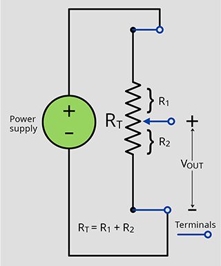
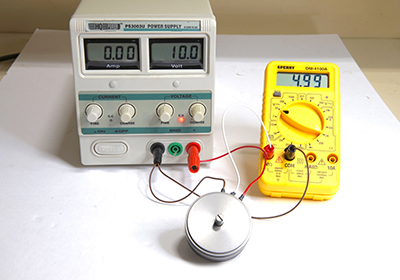
The photo and diagram show how these devices are connected to an input voltage when used in the most common configuration for controlling the output voltage by adjusting the device. The device could have a shaft that is turned by whatever it is attached to in the user’s application if it is a rotary potentiometer or angle sensor. If it is a linear sensor or potentiometer a shaft that slides would be attached to a linear moving part of the user’s application. The same principles apply if either of these types of sensors has a magnetic or inductive marker that is affixed to the moving part of an application with the sensor mounted on a non-moving part near the marker so it can sense the position of the marker.
The connections for all of these 3-wire analog output devices is the same. One side of the device is connected to a voltage input as represented by a power supply in the photo. The opposite side is connected to a ground (usually signal ground if separate from power supply ground). The sliding contact wiper is the output. The output voltage will vary depending on the position of the shaft or marker. Almost all applications can use a stable power supply for the input. The output will then be stable and vary between 0 V and the supply voltage according to Ohm’s Law. This proportional behavior is also referred to as "ratiometric."
The mid-point output, for example, is calculated using Ohm’s Law: V = I • R; and Kirchhoff’s Law states: the sum of the drop in voltages around a circuit loop equals the source voltage and the current enter a junction equals the current leaving that same junction. Putting all these laws together we can easily calculate the output voltage based on a known position of the sensor.
The sliding wiper contact should never be connected directly to the power supply or the ground. This would cause a short and likely destroy the sensor/potentiometer when the wiper was moved to one of the ends that would connect the power supply to ground.
|
The potentiometer or sensor can be viewed as a variable voltage divider. In our example, for the mid-point, the output would be calculated as shown here:
|
And R1 + R2 = RT , where RT is the total resistance across the end terminals.
So for example, say the power supply attached to Vin = 24 V and RT = 10 kΩ. When the potentiometer is turned so that the sliding wiper contact is connected to the power supply + input, the output voltage is 24 V. When it is turned to the opposite end, connecting the sliding wiper contact to the ground terminal, the output would be 0 V.
When the potentiometer is turned to mid-point the resistance of R1 = R2 = 5 kΩ, and the output would be:
|
Another area of importance is the aligning the direction of slope with the direction the shaft is turned. If your application requires a clockwise direction change to be increasing the output the + power supply should be connected to the R1 side and vice versa if your application requires a decreasing output as the shaft is turned clockwise. Test this and reverse the ground and + voltage connections if you are getting the opposite result needed for direction vs slope of output.
The output of a potentiometer should be connected to a high impedance device such as a signal conditioner or op-amp input. 10 MΩ or more is often recommended.
|
| | | |
Boom Extension Measurement and Control
| | | |
| | | |
|
|
De-icing airplanes is serious business, so in designing vehicles with apparatus to de- ice, nothing is left to chance. The de-icing spray is delivered to plane surfaces via a sprayer at the end of an extendable boom to lift the operator and sprayer to a working height above the wing of a plane. Novotechnik’s RSM 2800 magnetic encoder measures the 0 to 16 turns and angular position of the boom’s gearwheel with 16-bit resolution in a small package. The ±0.03% linearity contributes to the smooth and predictable movement of the boom.
Learn more.
|
| | | |
| | | |
| |
| Please email suggestions for technical subjects you would like to suggest for this newsletter to this link: Newsletter Editor |
| | | | |
| |
|