• The birth of the ion thrust airplane
• Sensor Tip: How to determine accuracy
• Application: Controlling forklift mast travel
• and more. |
To view newsletter in your browser click here.
|
|
First flight of ion thrust test airplane with 16.4 ft wingspan
Photo credit: MIT |
| | | |
| | | |
| | | |
Ion drive meets the airplane . . . and it flies
Ionic wind-propelled airplane with no moving parts
Photo credit: MIT |
|
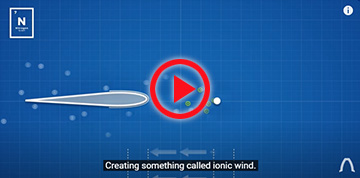
MIT researchers have built on the idea of ion propulsion technology from NASA and after seven years have created a flying model aircraft propelled by ionic wind created by ions in controlled motion.
Batteries and a custom designed step-up transformer and inverter create a 40,000 V high voltage differential charge between positively charged wires in front of negatively charged airfoils, creating ionic flow from wires to foils. This created a wind and airflow around the airfoil, creating lift and propulsion.1
The MIT team used a geometric programming optimization tool to determine an optimal design of wingspan, weight and other attributes. By means of comparison, a jet engine typically has a thrust to power ratio of 3 N/kW, a helicopter rotor can achieve 50 N/kW and the MIT ion powered plane reportedly has a power to thrust ratio of 6.25 N/kW.2
|
| | | |
Creating ionic wind
Photo credit: Real Engineering |
|
The plane flew 180 feet in an indoor test flight. As a point of reference, the Wright Brothers’ first flight went 120 feet, though subsequent flights that same day got them up to a flight distance of 852 feet in the air.3
|
| | | |
| | | |
 |
How to Determine Accuracy
|
|
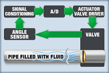
We need to start with an application, then determine the accuracy and precision that application requires as it relates to an angle/rotary-position sensor. Let's consider an hydraulic valve operation for an actuator and say the valve moving up to 90° needs to be controlled within ±1.0°.
Next, we need to create an error budget and assign maximum error amounts to each part that affects the accuracy of moving the valve. The components involved are represented by the block diagram at left.
|
| | | |
Each component in the application contributes to the error total including the fluid the valve is in contact with through its bulk modulus elasticity. However, closed-loop control can compensate for latent valve movement caused by fluid compression so, except for a small delay, we are left with adding up the tolerances of the angle sensor, signal conditioning circuitry, A/D converter, valve driver circuitry and hydraulic valve.
While we can add up the maximum tolerances of the components just mentioned, it will give a result that is a worst possible case. The worst case is unlikely, as all the errors from all the components would have to be operating at maximum error levels at the same time and in the same direction (positive versus negative error values). A more accurate way to calculate an error-budget is using the square root of the sum of the squares for each component, then add up the resulting errors. | READ ENTIRE ARTICLE INCLUDING EXAMPLE | |
| | | |
Controlling Forklift Mast Travel
| | | |
| | | |
|
|
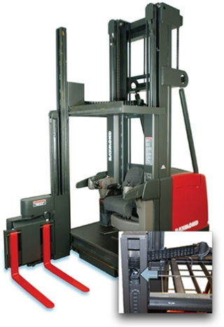
Raymond Corporation needed to measure and control the position of their forklift mast as it travelled vertically to move heavy boxes and other loads up and down. Their requirements matched a multi-turn sensor described below with repeatability of ±0.1%and independent linearity from 0.25 to 0.031%, depending on the number of turns.
Learn more.
|
| | | |
| | | |
 |
| |
| Please email suggestions for technical subjects you would like to suggest for this newsletter to this link: Newsletter Editor |
| | | | |
| |
|