• BMW Engineers reveal how they developed an E Ink car
• Sensor Tip: When choosing a Ratiometric Position Sensor may be the best choice
• Application: Positioning for automated trash retrieval
• and more.
|
|
Making the BMW iX Flow using E Ink. |
| | | |
| | | |
| | | |
Engineers Behind BMW’s E Ink Cars Reveal Development Process
| Color changing BMW iVision Dee concept car 2023 demo |
|
| E Ink is a company in Billerica Massachusetts that BMW tapped into to leverage their technology, brought from MIT’s Media Lab, to create vehicle exteriors that user selectable visual properties. The technology is called electrophoretic ink. When it is laminated onto a plastic film and connected to an electronic control module, it is referred to as an ePaper display.1 The “particle ink system” contains micro capsules of ink suspended in a clear fluid that change position when an electrical current is applied. Colored particles can be designed to respond to either a negative or positive charge, depending on color and move into different positions with respect to each other—depending on the charge on either side of two electrodes the particles are sandwiched in between.” |
| | | |
In 2002, BMW created iX Flow, a vehicle that could change color in sections between black and white. The process the engineers used is described by them in the top video link in this newsletter. In 2003 BMW used E Ink’s E Ink Prism™ 3 technology to create a concept car that provides a choice of 32 colors to 240 individually controllable E Ink segments on the car body.2,3 The video in this section shows that vehicle changing colors and demonstrates what is possible with this technology.
Other areas this technology is used in include book displays, digital writing "paper," wearables, retail store pricing/information displays, container tags, hospital patient-specific displays and transportation/way-finding signage. |
|
| | | |
| | | |
 |
When Choosing a Ratiometric Position Sensor May Be the Best Choice
Definition
Ratiometric sensors by definition are sensors where the output is directly proportional to the supply or excitation voltage. So, for example, if a 5 Volt excitation shows a 2.5V output, an increase in excitation to 5.5V (+10%) would create an output signal of 2.75V (+10%).
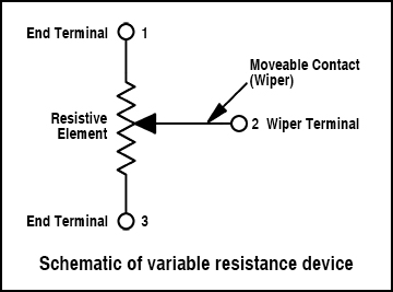
Ratiometric position sensors include variable resistor potentiometers connected between supply voltage and ground with the wiper as output, as well as Hall-Effect position sensors that are built around a variable resistor.
Benefits
The benefits described below may not be apparent at first sight, however, under the right circumstances can be advantageous and the better choice over other technologies.
If an existing measurement system consisting of a position sensor and a data acquisition device (can use the same voltage supply for excitation of the sensor and reference for the data acquisition system, the voltage supply can have a significant volatility range without impacting the precision of the measurement at all.
Application example
One example is on injection molding machines for polymer parts using linear potentiometers as position sensors. The low current consumption of a precision linear potentiometer ( e.g. our series TLH ) is typically 1 mA ( I=V/R, 10V/10kΩ= 0.001A ) so even a relatively weak reference voltage source, e.g. from the A to D converter in the data acquisition system, can provide for multiple potentiometer excitation.
Here’s the added benefit. All potentiometers used in voltage divider mode provide an extremely low temperature coefficient of about 5ppm/°K, which benefits measurement precision a lot, amounting only to 0.06% error over a temperature range of 125°C. In comparison, some very good active electronic sensors have an error of about 1.8% error over the same temperature range. |
|
|
Voltage divider mode means that the track is provided with the voltage potential of the supply on pin 1 and 3 and output voltage is picked up between the wiper – typically pin 2- and pin 3. The wiper at pin 2 picks up a voltage proportional to the track resistance between pin 1 and 2 relative to pin 2 and pin 3. With this relative measurement changes in resistance due to temperature of the potentiometer are self-compensated.
|
| | | |
Active, electronic position sensors that use advanced magnetic, capacitive or inductive technologies for the position measurement are usually built to work with supply voltage ranges between 3.3V and 35V, most of them covering parts of this wide range with a built-in supply stabilizer. Within their specified voltage supply range they show no change in output signal. If the data acquisition system is located in a different location, the supply voltage might be changing differently then on the site of the sensor, and errors due to that difference cannot be corrected.
There are also active sensors, especially rotary sensors with Hall-Effect Technology with e.g. 5V supply, which actually are ratiometric and provide the aforementioned benefit with volatile reference and excitation voltages and compensate for temperature swings with internal circuitry to a certain degree. The supply voltage can change typically within ±10% without impeding the ratiometric behaviour.
Choosing ratiometric position sensors over other position sensor technologies is often preferred for the following reasons.
1) If there are large temperature swings in the environment. When the position sensor is placed in an environment with a large variation in temperature, the output will remain within a very tight tolerance typically even up to 140° in temperature change when magneto-resistive and wire-wound varistor technologies would not.
2) When common reference voltages can be used for excitation and reference of the A/D converter. Here’s why: even small changes in either supply of the sensor or in the reference voltage will cause linearity errors larger than specified for the measurement system, but not ratiometric potentiometers
3) When a potentiometer is intended to be replaced and the same A/D converter or controller is to be used. This makes a design update quick and lower cost. |
| | | |
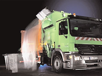
Lift and Tipping Positioning for Automated Trash Retrieval
| | | |
| | | |
|
|
The manufacturer of the waste disposal truck pictured here looked for value and reliability in a position sensor to monitor the lift and dump mechanism for its trucks. The Vert-X 28 excelled as it replaced four potentiometers with a single non-contact sensor that is impervious to dust and experiences no wear. The one sensor doing the job of four is possible because the Vert-X 28 series contains four functions in a single unit. These are a, b, c, d, Learn more about Vert-X 28 Series sensors.
|
| | | |
| | | |
 |
| |
| Please email suggestions for technical subjects you would like to suggest for this newsletter to this link: Newsletter Editor |
| | | | |
| |
|