 |
| CONTINUED... How to Integrate A Touchless Linear Sensor |
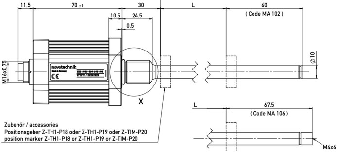
| Rod-type Linear Touchless Sensors These are linear touchless sensors intended to measure linear position of pistons inside of cylinders. However, they can also be used outside of cylinders for liquid level measurements and for measuring movements in applications, where there is simply not enough space for a larger aluminum extrusion type of sensor. In-cylinder sensors with magnetostrictive principle use a doughnut-shaped magnet marker mounted to the piston head. In order to point the magnetic fields on the sensor rod and not divert the field into the magnetic piston, the magnet marker should be mounted on a thick non-magnetic washer. The piston shaft is hollow to accommodate the sensor rod inside. Long strokes, e.g. larger than 500 mm, require a small support ring at the end of the sensor rod. There is usually a female thread option for the mounting bolt of the support ring. With the in-cylinder applications there is an option of mounting the sensor head (with its electronics) either inside or outside pressurized area. Outside makes sense if the diameter of the cylinder is smaller than the sensor housing, or if the customer wants easy access for maintenance purposes and where the base mount or swivel bushing are not in the way. The sensor is typically mounted via a 3⁄4 in or M18 thread with an SAE-type O-ring seat for proper sealing.
|
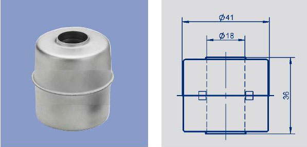
| This type of sensor housing is also ideal for tank level measurement by simply using a special float-type position marker.
|
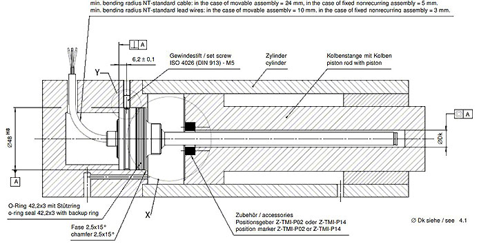
| Mounting a round version of the sensor head inside a hydraulic or pneumatic cylinder makes sense when the sensor needs to be protected from the environment as in construction vehicle hydraulic applications and when the cylinder uses a spherical bearing at the bottom end, leaving no space for a sensor head. The sensor head has a support O-ring seal on the outside to properly seal the pressurized cylinder side from the ambient pressure back side. The wiring is usually a pigtail with a connector on the outside of the cylinder or a cable that goes through a strain relief and to a junction box.
|
| Electrical Analog Interface |
| The electrical interface of choice depends on the controls used on the machine or measurement system. Many of the control systems for actuators of all kinds still use analog or current input signals coming from the position sensors, so let us start with the analog voltage output. The output voltage rises typically from 0.1 to 10 V when moving the marker from the start position near the connector end to the end position. The sensors come standard in 25 or 50 mm increment lengths and very long sensors in 100 mm increments. They require a three-wire connection between sensor and controls, supply voltage (V+ ), negative supply V- (GND), and the signal wire. This simple setup works great with short distances (<5 m /15 ft) and consequently low resistance of the wire. Longer wires, however, can cause an offset error caused by the voltage drop on the GND wire due to the supply current flow of approximately 70 mA. Therefore, active touchless sensors also allow for a 4-wire connection with a separate signal- for the signal output. This setup allows for cable lengths of 30 m or more – depending on the precision requirements and electromagnetic fields along the cable. The decision on when to switch to a 4-wire setup with two separate voltage inputs on the controls with differential signal conditioning strongly depends on the total resistance of the wires used and the precision required. An example: 3-wire setup with AWG20 / 0.5 mm2 copper wires with 33 MΩ /m in 10 m length results in a total resistance of 0.33Ω . With Ohm's law V=R•I and a sensor current consumption of 70 mA, the voltage drop across these wires equals 0.33 MΩ •70 mA = 23 mV. This voltage-drop is equivalent to 0.23% of the total output voltage range of 10 V.So this error is much larger than the specified linearity error of the sensor itself. The error might not be important in all applications, but it needs consideration. If the 4-wire setup with two voltage inputs on the controls is not an option, the current output option of many touchless sensors is the best option for very long wires (e.g. 200 m / 660 ft) in a 3-wire setup. The only limitation is that the resistance of the internal burden of the controls (usually around 250Ω ) plus the wire resistance cannot exceed 500Ω , which is easy to accomplish with the above mentioned AWG20 cable adding only 33Ω per 1,000 meters. The standard current output runs between 4 to 20 mA or 0 to 20mA over the total defined electrical stroke. The 4 to 20 mA current output is preferred in applications, where a broken wire in the circuitry needs to be detected. A current below 4 mA is considered out of range and signals some sort of trouble with lead wires, connectors or the sensor to the controller. Current outputs are used in long leads applications on valve controls, mobile applications like cranes and dump trucks. They are better suitable for long leads, noise rejection and contact resistance buildup in electrical connectors. AC Instrumentation Transducers are are beyond the scope of this paper and not covered here. |
| Electrical Digital Interface |
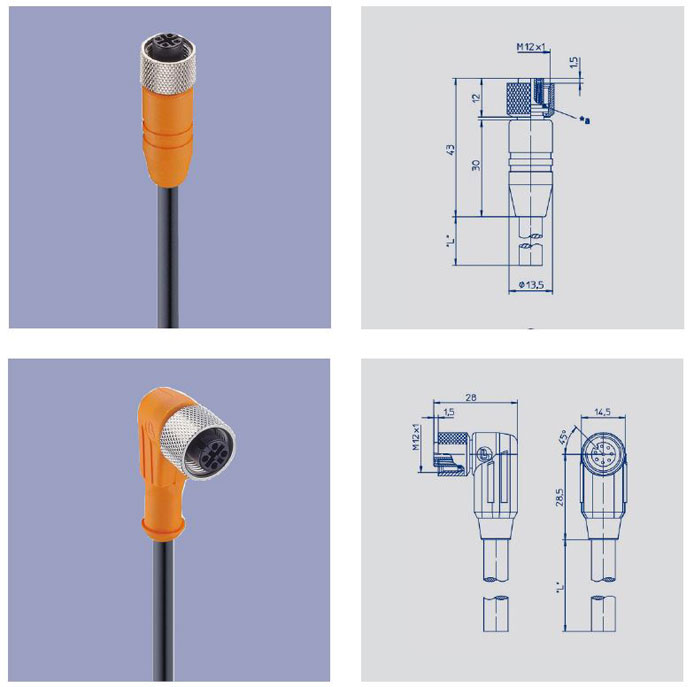
| There is a plethora of digital interfaces available for touchless linear sensors. Some of the most popular ones have been already discussed in prior Mechantronics Sense Newsletters Vol. 2 Issues 1through 4 and Volume 3 Issue 1. Cable Configurations and Connectors Cable and connector considerations are usually not on top of the engineer’s priority list, nevertheless they are important for reliable operation. The cable connection between the controller and the sensor provide the power supply to the sensor and the signal feedback from the sensor to the controller. Both run usually in the same jacketed cable, there are no issues as long as the power supply shows little AC ripple. The cable also protects the feedback signal against electric fields by providing different types of metal shields around the lead wires of supply and signal. There are braided shields available and braided shields with an aluminum foil shield added for increased high frequency noise rejection. Ferrite rings can be used instead or added on one or both ends of the cable connection, depending on the application specific EMC requirements. The shield provides usually the best protection against electrical fields when connected to measurement ground. To prevent ground loops, machine ground needs to be insulated from measurement ground by either insulating the sensors mounting points or by not connecting the shield to the sensor housing, which is preferable with aluminum extrusion sensor housings. Mechanical engineers need to decide, whether the sensor should come with a cable or a connector exiting the sensor housing. Highest ingression protection at reasonable cost is usually achieved with a sealed cable strain relief on the housing. If the sensor is mounted in a hard to reach location, it is advisable to use a cable connection with a connector placed where it is easy to reach for testing and calibration purposes. During the design-in phase of the sensor, engineers should check bending radiuses and cable support distances with the manufacturer for moving or static cable assemblies to prevent long term damage to the leads due to shaving, especially with vibration present in the application. Rubber grommets and cable ties help to restrain vibration and wear of the cable. Important requirements are also the chemical resistance of the cable jacket against aggressive hydraulic oils, the UV-resistance and the flammability. Sensors with a connector interface are preferable in cases where the required wiring needs to be different from sensor to sensor or when it is more practical to connect/disconnect all cables near the actuator or machine subsystem for maintenance and cleaning purposes, e. g. in the food or medical industry. Cables with over-molded M8 and M12 connectors are popular for both analog and digital interfaces of all kinds of industrial sensors. They come standard in several styles and lengths from various cable manufacturers. Customers can add their own connectors on the other end or have them customized by a cable assembly service. Some sensor manufacturers provide customized cable assemblies for their customers, e.g. specialized types of connectors for the marine environment. Connectors come in different seal ratings according to NEMA or IP-ratings. Tip: In wet environments, both ends need to be sealed properly, as liquids can wick through the air space left between the individual lead wires and can cause corrosion or shortcuts on components on the other side.
|